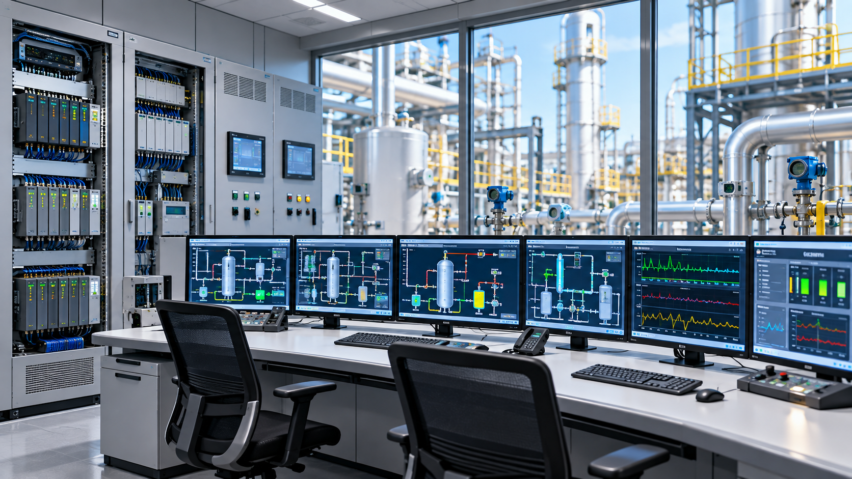
Distributed Control System (DCS) architecture is the structured arrangement of controllers, input/output modules, communication networks, operator workstations, engineering stations, and data servers that work together to automate industrial processes.
It distributes control functions across multiple locations while providing coordinated monitoring, communication, and supervision throughout an industrial facility.
Understanding DCS architecture helps engineers evaluate system scalability, network reliability, controller redundancy, industrial communication protocols, and integration with existing automation infrastructure. These architectural decisions influence plant availability, maintenance requirements, cybersecurity, and long-term expansion.
Quick Facts About DCS Architecture
Feature | Description |
|---|---|
Full Form | Distributed Control System |
Architecture Type | Distributed industrial control architecture |
Primary Function | Coordinated monitoring and process automation |
Control Structure | Multiple interconnected controllers |
Field Interface | Input/output modules |
Communication | Industrial control networks |
Operator Interface | Human-machine interface workstations |
Engineering Interface | Engineering workstations |
Data Management | Servers and process historians |
Reliability Features | Controller, network, and power redundancy |
Common Applications | Power generation, chemicals, oil and gas, pharmaceuticals |
Related Technologies | PLC, SCADA, SIS, industrial Ethernet |
Main Design Priorities | Availability, scalability, security, and interoperability |
What Is DCS Architecture?
DCS architecture describes how the hardware, software, communication infrastructure, and control functions of a Distributed Control System are organized.
Unlike a centralized control arrangement, where processing responsibilities are concentrated in one central controller, a DCS distributes control tasks among multiple controllers. Each controller manages an assigned process area while communicating with other system components through industrial networks.
A typical architecture includes several functional levels:
Field instrumentation for process measurements and equipment control.
Input/output subsystems for connecting field devices.
Distributed controllers for executing control strategies.
Control networks for communication between automation components.
Supervisory workstations for operator monitoring.
Engineering stations for system configuration.
Servers and historians for data management and reporting.
The architecture may be implemented differently depending on plant size, process complexity, availability requirements, and the selected automation platform.
Why DCS Architecture Matters in Industrial Automation
DCS architecture determines how industrial control functions are distributed, how information moves between system components, and how the facility responds to equipment or communication failures.
A well-engineered architecture separates critical control functions from less time-sensitive supervisory and information-processing activities. This separation helps maintain predictable control behavior while supporting plant-wide visibility.
Its main architectural benefits include:
Distributed processing: Multiple controllers handle different process areas.
Operational continuity: Redundant components can support continued operation during selected failures.
Scalable infrastructure: Additional controllers and I/O capacity can be incorporated through planned expansion.
Centralized supervision: Operators can monitor different plant sections through integrated workstations.
Communication flexibility: Industrial networks connect field-level and supervisory equipment.
System integration: Production information can be exchanged with manufacturing and enterprise applications.
Maintainability: Modular architecture can simplify fault isolation and component replacement.
These benefits depend on the quality of the engineering design. Distribution alone does not guarantee redundancy, cybersecurity, or uninterrupted operation.
Understanding the DCS Architecture Concept
Simple Explanation
Consider a chemical processing facility with separate areas for raw material preparation, reaction control, temperature regulation, and product handling.
Instead of using one controller to manage every operation, the DCS assigns control responsibilities to multiple controllers. Each controller processes information from its connected field devices and operates the equipment assigned to it.
All controllers communicate through an industrial control network. Operators use centralized workstations to observe the entire process, while engineering personnel configure and maintain the individual control functions.
This creates a distributed control environment with coordinated plant-wide supervision.
Centralized vs. Distributed Processing
In centralized processing, a major portion of the control logic depends on a single processing location. This can simplify certain small applications but may create limitations when the system expands.
Distributed processing assigns control tasks to separate controllers. A problem in one controller does not automatically disable every other controller, although the affected process area and any dependent functions may still be interrupted.
Functional Separation in DCS Architecture
Modern DCS designs distinguish between several functional responsibilities:
Real-time process control.
Field signal acquisition.
Operator supervision.
Engineering and configuration.
Historical data management.
Enterprise-level information exchange.
Keeping these responsibilities appropriately separated helps reduce unnecessary network traffic and protects time-critical control operations from unrelated information-processing workloads.
DCS Architecture Layers and Functional Hierarchy
A DCS is commonly understood through its functional layers. These layers describe where process measurements are collected, where control decisions are executed, how operators interact with the plant, and how production information reaches higher-level systems.
The ISA-95 framework provides a useful reference for understanding the relationship between industrial control and enterprise operations. Its hierarchy is a functional model, not a mandatory physical arrangement for every DCS installation.
Level 0: Physical Process Layer
Level 0 represents the actual industrial process and physical equipment being controlled. It includes production machinery, vessels, pipelines, pumps, motors, furnaces, boilers, and other process assets.
The DCS interacts with this layer through field instrumentation and actuators. Changes in physical conditions, such as pressure or temperature, are measured and used by the control system to determine appropriate operating responses.
Level 1: Field Instrumentation and Device Layer
Level 1 contains the instruments and devices that measure or manipulate the physical process.
Typical equipment includes:
Temperature transmitters.
Pressure transmitters.
Flow meters.
Level sensors.
Control valves.
Motor starters and variable frequency drives.
Analytical instruments.
Positioners and smart field devices.
These devices communicate process information to the DCS and receive control commands through appropriate input/output interfaces.
Level 2: Control and Supervisory Layer
Level 2 contains the primary DCS control infrastructure. It includes distributed controllers, I/O subsystems, operator stations, engineering stations, and associated control networks.
Controllers execute regulatory control loops, interlocks assigned to the basic process control system, sequences, and other configured control functions. Operator stations display process conditions, alarms, trends, and equipment status.
This layer is responsible for real-time process supervision and control.
Level 3: Manufacturing Operations Management Layer
Level 3 connects plant-floor control activities with broader manufacturing operations. It may include manufacturing execution systems, production scheduling, quality management, maintenance management, and production reporting applications.
Information from the DCS can help these systems evaluate process performance, production status, material usage, and operational history.
Level 4: Enterprise Planning and Business Layer
Level 4 represents enterprise-level planning and business activities. It commonly includes enterprise resource planning systems, business reporting, supply-chain management, and production planning.
Information exchanged with lower manufacturing levels supports business decisions without requiring enterprise applications to perform time-critical process control.
DCS Architecture Layer Comparison Table
Architecture Level | Main Components | Primary Responsibility | Typical Information |
|---|---|---|---|
Level 0 | Industrial equipment and processes | Physical production | Process conditions |
Level 1 | Sensors, transmitters, actuators | Measurement and manipulation | Field signals |
Level 2 | DCS controllers, I/O, HMI | Real-time control and supervision | Process values, alarms, commands |
Level 3 | MES and manufacturing applications | Production operations management | Production and quality records |
Level 4 | ERP and business applications | Enterprise planning | Business and resource information |
The exact implementation can vary. Not every DCS installation contains every level as a separate physical network or equipment group.
Detailed DCS Architecture Components
Distributed Process Controllers
Distributed controllers are the processing units responsible for executing assigned control strategies. They receive input data, perform calculations, evaluate control conditions, and issue output commands.
Controllers may manage separate plant areas, production units, or functional groups. Their configuration depends on the number of control loops, I/O capacity, processing requirements, communication interfaces, and availability objectives.
Common controller responsibilities include:
PID-based process regulation.
Equipment sequencing.
Process logic execution.
Alarm condition evaluation.
Communication with I/O subsystems.
Exchange of selected information with other controllers.
Remote Input/Output Systems
Remote I/O systems allow field signals to be connected to control infrastructure located away from the main controller cabinet. They reduce the need to route every individual field signal over long distances to a centralized equipment room.
Remote I/O may be distributed across production areas and connected through supported industrial communication networks. This arrangement can simplify installation and support modular plant expansion.
Human-Machine Interface Stations
Human-machine interface stations, commonly called HMI stations, provide operators with graphical access to the DCS.
Typical interface functions include:
Process overview displays.
Equipment status screens.
Alarm and event summaries.
Historical trend displays.
Operator command interfaces.
Process parameter visualization.
A well-designed HMI organizes information according to operational priorities so that operators can identify abnormal conditions and understand the state of the process.
Engineering Workstations
Engineering workstations are used to configure and maintain DCS applications. Authorized personnel use them to develop control strategies, configure I/O channels, modify graphical displays, manage alarms, and diagnose system issues.
Engineering access should be controlled because unauthorized configuration changes can affect industrial operations. Engineering activities should follow approved change-management and testing procedures.
DCS Application Servers
Servers support functions that are not necessarily executed directly by individual process controllers. Depending on the platform, these functions may include alarm management, application coordination, batch management, user authentication, reporting, and engineering data management.
Server architecture should account for availability, backup requirements, access permissions, and the effect of server failures on plant operation.
Process Historian
A process historian collects and stores time-series information from the control environment. It can record measurements, equipment states, operator events, and selected process conditions.
Historical records support:
Production analysis.
Process troubleshooting.
Performance evaluation.
Quality investigations.
Maintenance planning.
Operational reporting.
Historian availability and storage requirements depend on the volume, frequency, and retention period of collected data.
Industrial Communication Infrastructure
Communication networks connect controllers, I/O systems, operator workstations, servers, and other automation equipment.
Network design considers latency, bandwidth, reliability, topology, device compatibility, traffic prioritization, and cybersecurity boundaries. Control traffic must be engineered to meet the timing and availability requirements of the process.
Main DCS Architecture Components Table
Component | Architectural Location | Primary Function |
|---|---|---|
Field sensors | Field level | Measure process conditions |
Actuators | Field level | Manipulate process equipment |
Remote I/O | Control interface | Connect distributed field signals |
DCS controllers | Control layer | Execute control strategies |
Control network | Communication layer | Exchange automation data |
HMI stations | Supervisory layer | Display process information |
Engineering workstation | Engineering layer | Configure and maintain the DCS |
Application servers | System infrastructure | Support shared applications |
Process historian | Data management layer | Store historical process information |
Network switches | Communication infrastructure | Connect network devices |
Redundant power supplies | Infrastructure | Support power availability |
Types of DCS Architecture
DCS architecture can be classified according to the distribution of control equipment, communication arrangements, and system redundancy. These classifications describe different architectural approaches rather than separate process-control technologies.
Centralized I/O Architecture
In a centralized I/O arrangement, field signals are connected to I/O modules located in a common control equipment area or centralized cabinet arrangement.
Controllers process the acquired information and execute control functions. This design can be suitable for facilities where field devices are concentrated or cable routing to a central location is practical.
Advantages:
Centralized equipment organization.
Simplified access to I/O hardware.
Suitable for compact process installations.
Convenient equipment-room management.
Distributed I/O Architecture
Distributed I/O places I/O modules closer to the field equipment or across different plant areas. Remote I/O stations communicate with the associated control infrastructure through supported networks.
This arrangement can reduce extensive field cabling and support geographically distributed processes.
Advantages:
Flexible field-level installation.
Reduced long-distance signal cabling.
Modular expansion.
Suitable for large industrial facilities.
Redundant DCS Architecture
A redundant architecture duplicates selected components to reduce the consequences of individual hardware failures. Depending on the design, redundancy may be implemented for controllers, communication paths, power supplies, servers, or other critical infrastructure.
Redundant arrangements require appropriate fault detection, switchover mechanisms, synchronization, and testing.
Advantages:
Improved availability.
Reduced dependence on individual components.
Better tolerance of selected hardware failures.
Support for continuous industrial operations.
Integrated DCS Architecture
An integrated DCS architecture combines process control, supervisory monitoring, engineering, historical data, and selected manufacturing applications within a coordinated automation environment.
Integration can reduce information silos and simplify operational visibility, provided that appropriate network separation and access controls are maintained.
Advantages:
Coordinated plant-wide monitoring.
Shared operational information.
Consistent engineering practices.
Improved integration between control functions.
Virtualized DCS Architecture
Virtualization allows supported DCS server applications to operate within virtual machine environments rather than requiring a separate physical server for every application.
The arrangement can consolidate computing resources and simplify certain backup and recovery activities. However, it requires validated hardware, supported virtualization configurations, resource allocation, and careful network planning.
Advantages:
More flexible server resource management.
Reduced physical server requirements in suitable designs.
Simplified deployment of supported applications.
Improved flexibility for selected recovery arrangements.
DCS Architecture Type Comparison
Architecture Type | Main Arrangement | Key Advantage | Main Consideration |
|---|---|---|---|
Centralized I/O | I/O concentrated in equipment areas | Centralized hardware management | Field cabling requirements |
Distributed I/O | I/O positioned across plant areas | Flexible installation | Network design and remote access |
Redundant | Selected components duplicated | Higher availability | Additional engineering complexity |
Integrated | Multiple automation functions coordinated | Unified operational visibility | Integration and cybersecurity |
Virtualized | Supported applications hosted on virtual machines | Flexible computing infrastructure | Platform compatibility and validation |
These approaches can be combined. For example, a DCS may use distributed I/O, redundant controllers, and virtualized application servers within the same installation.
DCS Communication Architecture and Protocols
Communication infrastructure determines how information moves between field instruments, controllers, operator stations, servers, and external systems.
Industrial networks must support the required communication performance while maintaining suitable reliability and security boundaries.
Industrial Ethernet
Industrial Ethernet provides network connectivity for controllers, I/O stations, operator workstations, and servers. It supports high-capacity data exchange and can accommodate different industrial communication protocols.
Network engineering must consider traffic separation, redundancy, switch configuration, latency, and the environmental conditions of industrial installations.
FOUNDATION Fieldbus
FOUNDATION Fieldbus is an industrial communication technology used for process automation. It supports digital communication between compatible field devices and control infrastructure.
Depending on the implementation, field devices can exchange process information and diagnostic data over the fieldbus network.
PROFIBUS
PROFIBUS is an established industrial field communication family. PROFIBUS DP is commonly associated with distributed peripheral communication, while PROFIBUS PA is designed for process automation instrumentation.
It can be used to connect compatible field devices, remote I/O, and automation equipment.
HART Communication
Highway Addressable Remote Transducer, or HART, combines digital communication with an analog signal in supported implementations. It allows compatible instruments to transmit process information and additional device-related data.
HART is often used for instrument configuration, diagnostics, and access to device variables.
Modbus TCP and Modbus RTU
Modbus is an industrial communication protocol used to exchange data between compatible automation devices.
Modbus TCP operates over Ethernet networks, while Modbus RTU is commonly used over serial communication links. Both may be used for integrating selected meters, controllers, drives, and third-party equipment.
OPC UA
OPC Unified Architecture is a platform-independent framework for industrial data exchange. It supports structured information models, communication, and security mechanisms.
In DCS environments, OPC UA may support controlled information exchange between automation systems and higher-level manufacturing applications.
DCS Communication Protocol Comparison Table
Protocol | Communication Type | Common Application |
|---|---|---|
Industrial Ethernet | Ethernet-based networking | Controllers, servers, and workstations |
FOUNDATION Fieldbus | Digital field communication | Process instrumentation |
PROFIBUS DP | Fieldbus communication | Remote I/O and automation devices |
PROFIBUS PA | Process fieldbus | Process instruments |
HART | Analog and digital communication | Smart field instruments |
Modbus TCP | Ethernet-based communication | Equipment and system integration |
Modbus RTU | Serial communication | Meters and industrial devices |
OPC UA | Structured industrial information exchange | DCS and higher-level applications |
Protocol selection depends on existing infrastructure, supported equipment, timing requirements, interoperability, and security considerations. Not every protocol is intended for the same communication layer or control function.
DCS Architecture vs PLC Architecture vs SCADA Architecture
DCS, PLC, and SCADA technologies are closely related but serve different architectural roles. They may also be integrated within the same industrial automation environment.
A DCS provides distributed process control with coordinated operator supervision. A PLC is a programmable controller commonly used for machine-level and discrete control. SCADA provides supervisory monitoring and data acquisition across equipment or geographically distributed locations.
Feature | DCS Architecture | PLC Architecture | SCADA Architecture |
|---|---|---|---|
Primary role | Integrated process control | Programmable machine and equipment control | Supervisory monitoring |
Control arrangement | Multiple distributed controllers | Individual or networked controllers | Supervisory applications with underlying controllers |
Typical environment | Large process facilities | Machines and production equipment | Remote and distributed operations |
Operator interface | Integrated DCS HMI | HMI or supervisory interface | SCADA operator stations |
Data management | Integrated process historian options | External or integrated data systems | Supervisory databases and historians |
Expansion | Controller, I/O, and network expansion | Additional controllers and I/O | Additional sites and monitored devices |
Common applications | Chemical and power plants | Packaging and machine automation | Water distribution and pipeline monitoring |
DCS vs PLC: Architectural Difference
The primary distinction is the way control functions are organized and integrated. A DCS commonly provides a coordinated environment for many process areas, whereas PLC architectures are often organized around individual machines or equipment groups.
However, modern PLC platforms can support large, interconnected installations, and modern DCS platforms may include PLC-like functions. The distinction is therefore based on system architecture and application requirements rather than a simple rule about controller capability.
DCS vs SCADA: Architectural Difference
A DCS typically emphasizes integrated process control within a facility. SCADA emphasizes supervisory monitoring and data acquisition, often across remote assets and multiple locations.
SCADA systems can communicate with PLCs, remote terminal units, and other controllers. A DCS may also exchange information with SCADA applications where the plant architecture requires it.
DCS Network Topology and Redundancy Design
Network topology describes how controllers, switches, servers, and other automation devices are connected. The chosen arrangement affects communication availability, fault isolation, network expansion, and maintenance.
Star Topology
In a star arrangement, devices connect to a central network switch or switching infrastructure. This can make device connections easier to manage and faults easier to isolate.
However, failure of a central switching component can affect connected devices unless suitable redundancy is provided.
Ring Topology
In a ring arrangement, network devices are connected in a closed communication path. Supported industrial redundancy mechanisms can provide an alternate communication route when a link or device fails.
The actual recovery behavior depends on the selected protocol and network equipment.
Redundant Network Topology
A redundant network uses separate communication paths or switching arrangements to reduce the effect of individual network failures.
Redundancy may include separate switches, network interfaces, communication links, or independent network segments. The design must account for common points of failure, cable routing, and switchover behavior.
Segmented Network Architecture
Network segmentation separates communication environments according to their operational purpose and security requirements. For example, process-control traffic may be separated from enterprise information systems and external access networks.
This helps limit unnecessary communication and reduces the potential impact of security incidents.
DCS Network Topology Comparison Table
Topology | Arrangement | Main Advantage | Main Limitation |
|---|---|---|---|
Star | Devices connect through central switches | Straightforward management | Central switch dependency |
Ring | Devices form a communication loop | Supports alternate paths with suitable redundancy | Requires compatible recovery mechanisms |
Redundant network | Separate or duplicated communication paths | Improved communication availability | Higher complexity |
Segmented network | Networks separated by functional boundaries | Better traffic and security control | Requires careful configuration |
DCS Architecture Requirements and Infrastructure
A reliable DCS installation requires more than controllers and communication cables. Its infrastructure must support the electrical, environmental, operational, and cybersecurity requirements of the industrial facility.
Hardware Requirements
Hardware selection should account for process complexity, control-loop requirements, I/O capacity, communication interfaces, and environmental conditions.
Important considerations include:
Controller processing capacity.
Local and remote I/O compatibility.
Network interface availability.
Redundant hardware support.
Suitable industrial enclosures.
Equipment temperature and humidity ratings.
Power supply arrangements.
Spare capacity for future expansion.
Electrical and Power Requirements
DCS equipment requires stable electrical power to maintain controller operation, network communication, and operator visibility.
Critical components may use redundant power supplies and appropriately engineered uninterruptible power supply arrangements. Electrical distribution, grounding, protection, and backup arrangements should be designed according to the plant's availability and safety requirements.
Software and Engineering Requirements
DCS engineering involves configuring control logic, process graphics, alarms, communication settings, and system databases.
The engineering environment should support:
Controller configuration.
I/O database management.
Control-loop configuration.
Alarm and event management.
Operator display development.
System diagnostics.
Configuration backup and recovery.
Controlled application changes.
Environmental Requirements
Industrial equipment may operate in areas exposed to heat, vibration, dust, humidity, or corrosive atmospheres. Control cabinets, network devices, and field interfaces must be suitable for their installation environments.
Equipment selection should also consider hazardous-area classification where applicable.
Cybersecurity Requirements
DCS infrastructure should include security controls appropriate for industrial control environments.
Typical measures include network segmentation, restricted engineering access, controlled remote connections, account management, security monitoring, and tested backup arrangements.
DCS Architecture Implementation Workflow
Implementing a DCS architecture requires coordinated process engineering, instrumentation, electrical design, automation engineering, and cybersecurity planning.
Step 1: Define Process and Operational Requirements
Identify the industrial processes that require automation, including control loops, equipment sequences, operator functions, production constraints, and availability requirements.
Step 2: Develop the Control System Design
Establish the control philosophy, controller distribution, I/O requirements, operator interface arrangements, and system boundaries.
Step 3: Design the Network Architecture
Define control networks, communication interfaces, network segmentation, redundancy arrangements, and connections to external systems.
Step 4: Select Hardware and System Capacity
Evaluate controller capacity, I/O modules, network equipment, servers, workstations, and power infrastructure against the engineering requirements.
Step 5: Configure Control Applications
Develop control strategies, equipment logic, process displays, alarm configurations, and communication settings.
Step 6: Integrate Field Instruments
Connect field devices, verify signal assignments, check communication compatibility, and confirm that instrumentation information is correctly represented in the control system.
Step 7: Test and Validate the Architecture
Perform appropriate hardware, software, communication, and functional testing. Factory acceptance testing and site acceptance testing are commonly used within industrial project delivery.
Step 8: Commission and Handover
Commissioning verifies that the installed system operates according to its design requirements. Handover should include approved documentation, configuration backups, operating procedures, and maintenance information.
DCS Architecture Implementation Workflow Table
Implementation Stage | Main Activity | Expected Output |
|---|---|---|
Requirements | Process and control assessment | Functional requirements |
Architecture design | Controller and system organization | DCS architecture documents |
Network design | Communication and security planning | Network architecture |
Hardware selection | Equipment and capacity evaluation | Hardware specifications |
Engineering | Control logic and interface configuration | Configured applications |
Integration | Field and system connectivity | Integrated control environment |
Testing | Functional and communication verification | Test records |
Commissioning | Operational validation | Commissioned DCS |
Handover | Documentation and training | Operational handover package |
Industry Applications of DCS Architecture
Oil and Gas Processing
Oil and gas facilities use DCS architecture to coordinate process units, pressure regulation, temperature control, flow management, and equipment monitoring.
Refineries and processing plants often contain multiple interconnected production areas. Distributed controllers allow these areas to execute assigned control strategies while operators maintain centralized supervision.
Chemical Manufacturing
Chemical plants use DCS architecture to manage reaction processes, mixing, temperature regulation, pressure control, and material transfer.
The architecture supports coordination between process units and provides access to alarms, historical data, and operating parameters.
Power Generation
Power plants use DCS platforms to supervise boilers, turbines, generators, cooling systems, and auxiliary equipment.
Controller distribution and appropriate redundancy arrangements help support continuous operation and coordinated monitoring of interconnected plant systems.
Pharmaceutical Manufacturing
Pharmaceutical production environments use DCS architecture for process automation, batch operations, temperature control, material handling, and production monitoring.
System configuration may also support electronic records, access controls, and process traceability according to applicable regulatory requirements.
Water and Wastewater Treatment
Water treatment facilities use distributed automation to supervise filtration, chemical dosing, pumping, flow regulation, and treatment processes.
DCS architecture can integrate multiple process areas while providing operators with centralized visibility into equipment status and operating conditions.
Pulp and Paper Manufacturing
Pulp and paper facilities use DCS infrastructure to coordinate pulping, chemical preparation, drying, material handling, and production processes.
Integrated process monitoring helps operators observe production conditions across interconnected manufacturing stages.
Industry Applications of DCS Architecture Table
Industry | Main Automation Areas | Architectural Requirement |
|---|---|---|
Oil and gas | Refining and process regulation | Distributed process control |
Chemicals | Reaction and material processing | Coordinated control loops |
Power generation | Boiler and turbine systems | High availability |
Pharmaceuticals | Batch and process automation | Traceability and controlled access |
Water treatment | Filtration and pumping | Distributed monitoring |
Pulp and paper | Production process control | Integrated plant supervision |
Cement manufacturing | Kilns and material handling | Process coordination |
Food processing | Mixing and thermal processing | Batch and continuous control |
DCS Architecture Standards and Industrial Safety
DCS architecture should be developed with relevant industrial automation, functional safety, cybersecurity, and integration standards in mind. The applicable requirements depend on the process, jurisdiction, system boundaries, and intended functions.
ISA-95: Enterprise-Control System Integration
ANSI/ISA-95, also known as IEC 62264, defines models and terminology for exchanging information between manufacturing control functions and enterprise functions.
It provides a reference for organizing the relationship between process control, manufacturing operations management, and business planning.
ISA/IEC 62443: Industrial Automation and Control Systems Security
The ISA/IEC 62443 series addresses cybersecurity requirements for industrial automation and control systems.
Its framework includes security requirements, risk assessment, system segmentation, and lifecycle security practices. It is relevant when designing DCS network boundaries, access controls, and secure connections.
IEC 61131-3: Programmable Controller Programming Languages
IEC 61131-3 specifies programming language syntax and semantics for programmable controllers. It covers languages and structures including Structured Text, Ladder Diagram, Function Block Diagram, and Sequential Function Chart.
Its relevance depends on the controller platform and engineering implementation.
IEC 61511: Functional Safety
IEC 61511 addresses functional safety requirements for safety instrumented systems in the process industry.
A safety instrumented system is not simply another DCS control application. Safety functions require appropriate lifecycle management, independence considerations, verification, and validation.
IEC 61508: Functional Safety of Electrical and Electronic Systems
IEC 61508 provides a broader functional safety framework for electrical, electronic, and programmable electronic safety-related systems.
It establishes principles relevant to the development and use of safety-related equipment and systems.
Industrial Safety and Cybersecurity Separation
Basic process control and safety instrumented functions should be engineered according to their respective requirements. Their interaction, independence, communication arrangements, and failure behavior must be assessed rather than assumed.
Common DCS Architecture Challenges and Solutions
Challenge | Possible Cause | Appropriate Solution |
|---|---|---|
Controller overload | Insufficient processing capacity | Review controller loading and task execution |
Network communication failures | Hardware faults or poor network design | Improve diagnostics and communication redundancy |
I/O signal errors | Incorrect configuration or wiring faults | Perform signal verification and loop testing |
Integration difficulties | Incompatible protocols or data models | Define integration interfaces early |
Excessive network traffic | Unnecessary data exchange | Review traffic patterns and segmentation |
Configuration inconsistencies | Uncontrolled engineering changes | Establish configuration management |
Server availability problems | Hardware or application failures | Evaluate redundancy and recovery arrangements |
Cybersecurity vulnerabilities | Weak access controls or exposed connections | Apply industrial cybersecurity controls |
Limited expansion capacity | Insufficient spare I/O or processing resources | Plan capacity and expansion requirements |
Legacy equipment compatibility | Older interfaces and unsupported components | Develop a controlled integration or migration strategy |
Challenges should be evaluated at the system level. Replacing one component without assessing its network connections, application dependencies, and operational role can introduce additional problems.
How to Choose a DCS Architecture
Selecting an appropriate DCS architecture requires matching the system design to the process, facility layout, availability requirements, and future operational plans.
Selection Factor | Evaluation Criteria | Architectural Impact |
|---|---|---|
Process complexity | Number and interaction of control loops | Controller distribution |
Plant size | Number of process areas and devices | System organization |
I/O capacity | Current and expected field signals | Local or remote I/O design |
Availability | Acceptable failure and recovery conditions | Redundant infrastructure |
Network requirements | Communication timing and traffic | Network topology |
Cybersecurity | Threat exposure and security boundaries | Segmentation and access controls |
Integration | Existing PLC, SCADA, and enterprise systems | Protocol and interface selection |
Expansion | Future process and equipment additions | Spare capacity and modular design |
Maintenance | Available engineering resources | Standardization and diagnostics |
Lifecycle requirements | Support, migration, and obsolescence | Long-term architecture planning |
Architecture Selection by Application
Small process facilities: A compact controller and I/O arrangement may be sufficient when process requirements and availability expectations are limited.
Large process plants: Distributed controllers and remote I/O can support geographically separated production areas.
Continuous operations: Redundant controllers, networks, and power arrangements may be appropriate where interruption consequences are significant.
Multi-unit facilities: Integrated operator stations and process historians can support centralized supervision.
Digitally connected plants: Segmented networks and controlled data interfaces can support manufacturing and enterprise integration.
The final design should be based on a documented control philosophy, risk assessment, and engineering evaluation rather than equipment specifications alone.
DCS Architecture Maintenance Best Practices
Controller Health Monitoring
Monitor controller diagnostics, processor loading, memory utilization, communication status, and fault indicators. Abnormal conditions should be investigated according to approved maintenance procedures.
Network Performance Monitoring
Review communication errors, network availability, device status, and traffic behavior. Periodic network assessments can help identify failing connections or capacity constraints.
I/O System Inspection
Check I/O module health, channel status, field wiring, communication interfaces, and signal quality. Changes to field devices should be reflected in approved system documentation.
Configuration Backup
Maintain controlled backups of controller applications, HMI configurations, system databases, network settings, and other required engineering records.
Backup procedures should include restoration testing rather than relying only on the existence of stored files.
Redundancy Testing
Where redundant controllers, networks, servers, or power supplies are installed, test their intended failover behavior according to approved procedures.
Redundancy should not be assumed to work correctly without periodic verification.
Cybersecurity Maintenance
Review user accounts, access permissions, remote connections, security monitoring, and approved updates. Changes should be coordinated with operations because some security activities can affect control system availability.
Documentation Management
Maintain updated architecture diagrams, network drawings, I/O lists, control narratives, communication configurations, and maintenance records.
Accurate documentation helps engineers troubleshoot faults and plan system changes without introducing unnecessary operational risks.
DCS Architecture Limitations
Although distributed control architecture provides flexibility, it introduces engineering and operational considerations that must be addressed.
System Complexity
A DCS may contain numerous controllers, networks, I/O modules, workstations, servers, and application dependencies. Designing and maintaining these interconnected components requires specialized automation knowledge.
Higher Infrastructure Requirements
Large installations may require substantial control hardware, communication infrastructure, engineering resources, and dedicated equipment areas.
Vendor Dependency
Some DCS platforms use proprietary engineering environments, hardware interfaces, or communication mechanisms. This can affect future integration, component replacement, and migration planning.
Cybersecurity Exposure
Network connectivity creates potential attack paths. Incorrect segmentation, weak access controls, or poorly managed remote connections can expose industrial operations to cybersecurity threats.
Migration Challenges
Replacing a legacy DCS can involve complex control logic, undocumented interfaces, historical data, and production dependencies. Migration requires careful planning, validation, and controlled commissioning.
Redundancy Does Not Eliminate Every Failure
Duplicated components can reduce the impact of selected hardware faults, but common-mode failures, software defects, configuration errors, and external disruptions can still affect system availability.
Future Trends in DCS Architecture
Software-Defined and Virtualized Infrastructure
Virtualized server environments are changing how selected DCS applications are deployed and maintained. They can provide more flexible computing arrangements, although supported configurations must be validated for industrial use.
Industrial Edge Computing
Edge computing allows selected data-processing activities to occur closer to industrial equipment. It can support local analytics and information processing without requiring every application to depend on centralized computing infrastructure.
OPC UA-Based Integration
Standardized information exchange is increasingly relevant as manufacturers connect process control systems with manufacturing operations and enterprise applications. OPC UA supports structured industrial data communication across compatible systems.
Industrial Cybersecurity by Design
Modern architecture increasingly incorporates security into initial system design. Segmentation, restricted access, monitoring, and controlled data exchange are becoming important considerations throughout the DCS lifecycle.
Advanced Process Analytics
Industrial analytics can use historical and real-time process information to identify operating patterns, support optimization, and improve maintenance planning.
These capabilities complement the underlying control architecture rather than replacing the need for reliable deterministic process control.
Modernization of Legacy DCS Platforms
Many facilities continue to operate older control systems. Modernization projects increasingly focus on upgrading communication infrastructure, replacing obsolete components, improving cybersecurity, and integrating historical systems with newer manufacturing applications.
Frequently Asked Questions About DCS Architecture
1. What are the main layers of DCS architecture?
DCS architecture is commonly described through five functional levels: physical processes, field instrumentation, control and supervision, manufacturing operations management, and enterprise planning. These levels help explain how information moves between industrial equipment, control systems, and business applications.
2. What are the main components of DCS architecture?
The main components include distributed controllers, input/output modules, field instruments, communication networks, HMI workstations, engineering stations, application servers, and process historians. Each component performs a specific function within the overall automation infrastructure.
3. What is the difference between centralized and distributed I/O architecture?
Centralized I/O places input/output modules in a common equipment location, while distributed I/O positions modules closer to field equipment. Distributed I/O can reduce long field cable runs and provide more flexible installation arrangements.
4. Why is redundancy important in DCS architecture?
Redundancy helps reduce the impact of selected hardware or communication failures by providing alternative components or paths. It can improve system availability, although it does not eliminate every possible failure.
5. Which communication protocols are used in DCS architecture?
Common technologies and protocols include Industrial Ethernet, FOUNDATION Fieldbus, PROFIBUS, HART, Modbus TCP, Modbus RTU, and OPC UA. Their applications differ according to the communication layer, device compatibility, and process requirements.
6. What is the difference between DCS and SCADA architecture?
DCS architecture generally focuses on integrated process control within an industrial facility. SCADA architecture primarily provides supervisory monitoring and data acquisition, often across remote locations and distributed assets.
7. How does ISA-95 relate to DCS architecture?
ISA-95 provides a framework for organizing information exchange between industrial control functions, manufacturing operations, and enterprise systems. It helps define the boundaries between process automation and higher-level production and business applications.
8. What is a redundant controller in a DCS?
A redundant controller arrangement uses duplicated controller hardware or supported controller configurations to improve availability. If the active controller experiences a qualifying fault, the standby arrangement may take over according to the platform's redundancy design.
9. Can DCS architecture integrate with PLC and SCADA systems?
Yes. DCS platforms can exchange information with PLCs, SCADA applications, historians, and manufacturing systems through compatible communication interfaces. Integration requires appropriate data mapping, network design, security controls, and testing.
10. What should be considered when designing DCS architecture?
Important considerations include process complexity, controller capacity, I/O distribution, communication performance, redundancy, cybersecurity, integration requirements, and future expansion. The architecture should also address maintenance, system lifecycle, and operational availability.
Conclusion
DCS architecture provides the structural foundation for modern industrial process automation. Its combination of distributed controllers, field instrumentation, communication networks, operator interfaces, engineering workstations, and data management infrastructure supports coordinated plant-wide control.
Understanding architecture layers, network topologies, redundancy arrangements, communication protocols, and industrial integration standards helps engineers develop reliable and scalable automation environments. Careful design, cybersecurity planning, lifecycle management, and system validation remain essential for long-term DCS performance.